
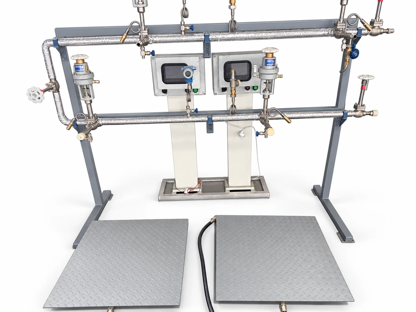
A gas filling system turns a gas supply into filled cylinders: compressed cryogenic media, prepared gas mixtures, liquefied petroleum gas (LPG) or, as an adjacent line, dry ice. For nitrogen, oxygen, argon and CO2 the supply is usually a stored cryogenic liquid, raised to filling pressure by a pump and, where gas-phase filling is required, vaporized before it reaches the cylinders. LPG is transferred as a liquid from storage, and each cylinder is filled by weight at a filling post. Cryofortune Engineer & Supply Co., Ltd. sources the equipment from a network of Chinese manufacturers. For compressed gases, mixtures and dry ice it covers each stage of the chain: the factory is selected per destination country, design standard and documentation requirement, and the stages are sized together as one duty. For LPG the scope is the filling-post equipment only; LPG storage, pumps and compressors, station piping and station design stay with the operator and its engineer.
What a filling station comprises
Stations filling compressed gases from a liquid supply reduce to five functional blocks. A liquid reserve holds the media. A pump raises it to filling pressure. A vaporizer converts liquid to gas where gas-phase filling is required. A filling manifold, or ramp, distributes flow to the cylinder connections. Controls and instrumentation supervise pressure, temperature and shut-off.
- Liquid reserve. A vertical cryogenic storage tank of 7,990–25,000 L gross volume and 0.8–2.2 MPa working pressure suits continuous filling duties. Lower-throughput sites can start from vertical cryogenic cylinders of 50–500 L gross volume with built-in pressure build-up.
- Pressure raising. Reciprocating filling pumps and pump skids handle liquid transfer and high-pressure cylinder filling; their ratings are set out in the core line below.
- Regasification. Ambient-air and heated vaporizers (the ambient air vaporizer line reaches 10,000 Nm³/h) supply the gas phase where gas filling is required.
- Manifolds and controls. Filling ramps, valve stations and instrumentation are configured as part of packaged supply, against cylinder count and connection type.
Filling cylinders from a liquid supply
The core line is short: tank, pump, vaporizer, manifold. A cryogenic cylinder filling pump takes liquid at 0.3–0.8 MPa inlet pressure and discharges at 16–25 MPa, at flow rates of 800–1,000 L/h with 7.5–11 kW motors, for LN2, LOX, LAr and liquid CO2. A high-pressure cryogenic vaporizer rated up to 200 bar working pressure converts the discharged liquid to gas ahead of the manifold. The gas then fills seamless high pressure gas cylinders of 5–50 L water capacity at working pressures of 150–300 bar, with the catalog line manufactured to ISO 9809-1; cylinder approval requirements are confirmed per destination market. Pump, vaporizer and cylinders are selected together against the target filling pressure — the figures above are per-model ranges, not a single guaranteed chain.
Pump selection is treated in how to choose a cryogenic cylinder filling pump, and vaporizer capacity in the vaporizer sizing guide. Both are sized against cylinders filled per shift rather than against nameplate maxima.
Distributors that also refill and deliver liquid cylinders can plan those rounds from real levels. With a CryoFor TM2 module on each customer’s cylinder, CryoFor Telemetry for gas distributors shows every customer’s reserve on one screen, and run-out forecasts let refills be scheduled before they become rush deliveries; planning deliveries by level walks through the approach.
CO2 filling and outlet temperature
CO2 lines usually add a heating stage. After vaporization, a gas heater / CO2 heater stabilizes outlet gas temperature, with variants rated 2–25 MPa, 100–300 m³/h and 24–96 kW at 380 V. The CO2 filling station equipment setup article sets out a complete line stage by stage, from storage through heater to manifold.
Where gas mixtures are filled
Stations filling Ar+CO2, Ar+O2, Ar+He or N2+CO2 blends — welding shielding and food-packaging duties — insert a mixing stage between supply and manifold. A gas mixer with buffer tank delivers 50–300 m³/h at an adjustable 0.05–0.6 MPa outlet (0.3–0.5 MPa on 50 m³/h units), with mixing accuracy of 0.5–1%. Where dosing, pressure regulation and operator monitoring are centralized, a gas mixing cabinet with PLC control takes the same duty at 100–300 m³/h. A standalone gas mixture buffer tank of 600 L or 2,000 L, rated 0.8 MPa, stabilizes line pressure downstream of the mixer.
Dry ice production as an adjacent station
Sites holding liquid CO2 often add a dry-ice line drawing from the same reserve. A dry ice pelletizer converts liquid CO2 into pellets of 3 mm or 16 mm at 40–50 kg/h from a 3 kW drive. Insulated dry ice storage containers of 33–350 L limit sublimation loss between production and dispatch.
LPG cylinder filling
LPG cylinders are filled by weight rather than from a vaporized supply. At each filling post the cylinder stands on an electronic filling scale that cuts off the fill at a preset mass and, with an optional cylinder scanner and registry, refuses cylinders that should not be filled. We source this filling-post equipment; LPG storage, pumps and compressors, station piping and station design are outside that scope. The LPG cylinder filling scales page sets out the specification and ten checks to make before ordering, and Ex certification for LPG filling equipment compares ATEX, IECEx, EAC, China’s CCC and Taiwan’s registration.
Filling station layout, safety and standards
Filling stations attract closer regulatory attention than standalone storage. Cylinder-handling areas, venting, separation distances and electrical supply are governed by destination-country rules, and pressure-equipment codes may apply to individual vessels and pumps. Requirements differ by market and are confirmed per project; the standards hub outlines the main frameworks, and export certification covers the documentation that accompanies shipment.
Articles
- Cylinder filling module
- Cryogenic loading skid
- Gas mixing system and buffer tank
- Welding shielding gas mixtures
- Dry ice production equipment chain
Scoping a filling system
Five parameters fix most configurations: the media, cylinders filled per day, target filling pressure, any mixture requirement, and the site’s available power. The equipment-by-gas guide helps where the media itself is still being settled; storage sizing follows from the same daily-throughput figure and is fixed in the configuration proposal. LPG filling posts are scoped differently, by cylinder sizes, the zone at the post and the destination market; see the ten checks on the LPG cylinder filling scales page.
Send a rough duty description — media, cylinders per day, target filling pressure and destination country — and we will return a configuration proposal with a manufacturer matched to your market. Configurations and documentation are confirmed for the specific manufacturer, model and order before production.
Weight-based filling guide
Weight-Based Filling Stations for Gas Cylinders and Liquid Cylinders
Review weighing posts, vessel connections and the details needed to configure equipment for the gas and vessel.
Tell us about your filling task
Share the gas, required filling output, pressure and destination country. Unknown details can be confirmed later.
Send a filling inquiry