
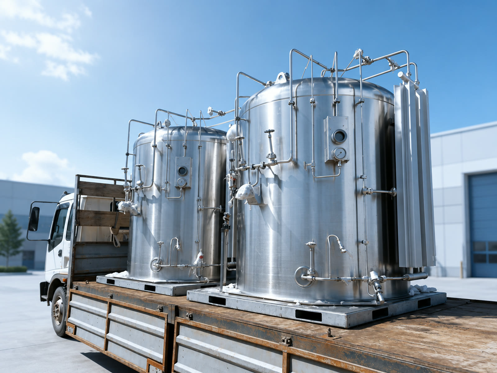
Carbon dioxide is the outlier among the industrial-gas media, and the equipment for it reflects that. Liquid CO2 is stored at a higher temperature and a substantially higher pressure than deep-cryogenic liquids such as nitrogen or argon. That difference shifts vessel pressure ratings, changes the vaporization stage and adds a production chain — dry ice — that no other medium has. This page maps our CO2-capable equipment to the applications where it typically runs.
How CO2 service differs from deep-cryogenic media
Nitrogen, oxygen and argon are held near atmospheric pressure at very low temperature, and ambient-air vaporizers usually carry the regasification duty. Liquid CO2 is held under pressure at a moderate low temperature, and sustained gas draw pulls heat out of the liquid quickly. In many CO2 duties an electric or steam-assisted heater therefore supplements the ambient stage, stabilizing gas temperature after vaporization. The gas heater / CO2 heater line covers seven variants rated 2–25 MPa, with capacities of 100–300 m³/h and heating power from 24 to 96 kW. Where an ambient stage carries the duty on its own, the cryogenic vaporizer range includes CO2 configurations. The comparison in equipment by gas covers this reasoning in more detail.
Beverage carbonation and breweries
Breweries, soft-drink bottlers and co-packers draw CO2 for carbonation, tank purging and counter-pressure filling. Smaller sites usually run vertical cryogenic cylinders, available in 21 variants from 50 to 500 L with built-in pressure build-up. Plants with continuous demand move to a vertical storage tank in a CO2 configuration, with gross volumes of 7,990–25,000 L and working pressures up to 2.2 MPa. The article on when to upgrade from cylinders outlines where that threshold usually sits.
Liquid CO2 cylinders can report their level remotely as well. A CryoFor TM2 module takes the place of the stock electronic level gauge, reads the vessel’s own capacitive level probe with the density set for CO2, and reports on a set schedule to CryoFor Telemetry; pressure is added once a separate pressure sensor is fitted. TM2 is a monitoring device, not a measuring instrument for commercial gas metering.
Food chilling and modified-atmosphere packaging
Food processors use CO2 for chilling, crust freezing and as a component of MAP blends. Chilling duties combine bulk storage with a vaporizer and heater sized to the line’s peak flow rather than its average. MAP lines typically run N2+CO2 mixtures, prepared by the same gas-mixing equipment described under welding blends below. The mixture composition and outlet pressure are configured for the packaging machine at order stage.
Dry ice production and handling
Dry ice is the one product chain unique to CO2, and it is a compact one. The dry ice pelletizer (HR-KL-50) converts liquid CO2 into pellets of 3 mm or 16 mm at 40–50 kg/h, drawing 3 kW. Feed liquid comes from a storage tank or cryogenic cylinders installed beside the machine. Finished pellets go into dry ice storage containers — insulated PE boxes in nine sizes from 33 to 350 L that limit sublimation loss during holding and transport. Pelletizer, containers and the liquid-supply vessel are normally quoted together as one production cell.
Welding shielding blends
Ar+CO2 mixtures carry most MAG welding, and N2+CO2 blends serve food packaging from the same equipment family. Blend preparation is handled by the gas mixer with buffer tank or the PLC gas mixing cabinet, with a standalone gas mixture buffer tank stabilizing line pressure downstream; full configurations and specifications sit on those product pages. On the CO2 side of the blend, the selection question is the same as elsewhere on this page — a liquid supply vessel and vaporization sized to the CO2 fraction of the mixture flow. How the argon side is stored is compared in equipment by gas.
CO2 for water treatment and pH control
Water plants inject CO2 for pH control and remineralization, where it displaces mineral acids in many flowsheets. The duty is a steady, moderate gas flow, normally served by a storage tank with a heater matched to the dosing curve. Equipment selection follows the same tank-plus-heater logic as beverage service, sized from dosing demand rather than peak process draw.
CO2 filling stations and distribution
Distributors filling CO2 cylinders pair a cryogenic cylinder filling pump — 800–1,000 L/h flow, discharge pressure 16–25 MPa — with high pressure gas cylinders of 5–50 L rated 150–300 bar and manufactured to ISO 9809-1. The layout of a complete station is described in CO2 filling station equipment setup, and pump selection in the filling pump guide. For bulk movement of liquid CO2, the 20 ft cryogenic tank container offers 17.5–21.13 m³ gross volume in a transportable ISO frame.
Standards and destination
CO2 vessels, cylinders and filling equipment fall under pressure-equipment and transport rules that differ by destination country. Because we source from a network of Chinese manufacturers, the factory for a CO2 order is selected against the destination’s design codes and documentation requirements. Which standards may apply is summarized on the standards hub, with a worked country example for Australia and the paperwork itself in the export certification guide.
Configurations and documentation are confirmed for the specific manufacturer, model and order before production. Send a rough duty description — application, daily CO2 consumption in kg, peak gas flow and destination country — and we will return a proposed configuration with the matching factory.